CAD: Lever In An Aircraft
- anandapermata

- Sep 7, 2021
- 2 min read
Lever is used to create more force on the short arm with less force on the long arm or to get more movement on the long arm and less movement on the short arm.
A lever is a basic mechanism with a fulcrum and a stiff beam. On either end of the beam, the effort (input force) and load (output force) are applied. The fulcrum is the pivot point of the beam. A weight is applied to the other end of the lever when an effort is put to one end of the lever.
Lever is used to create more force on the short arm with less force on the long arm or to get more movement on the long arm and less movement on the short arm. If we make the lever arm long enough, in theory, any effort can be developed.
There are three types of levers: first, second and three class. The difference between the three classes is determined by the location of the force, the fulcrum, and the load.
The fulcrum of first-class levers is located between the force and the load. In a first-class lever, the effort (force) travels a long distance in order to move the load a short distance, and the fulcrum is located between the effort (force) and the load.
Second class levers, the load is between the force (effort) and the fulcrum. In this type of levers, the effort moves over a large distance to raise a load a small distance.
Third class levers has the load between effort (force) and the fulcrum.[1]
There are a lot of levers implementation and in this case is in aircraft applications. The main levers on an aircraft are engine control levers (throttle levers). By acting on the lever, the engine thrust is changed. An increase in thrust leads to an acceleration of the apparatus, a decrease in a deceleration. With an increase in traction, fuel consumption increases. If a person wants to know how to adjust the control of aircraft, it will be necessary to study the optimal positions of the lever and thrust of the aircraft in different situations.
During flight, the engine control lever is almost always set to idle to conserve fuel. It is necessary to correct the position of the lever based on the readings of the instruments. The fighter is controlled in the same way as the control of a private or multipurpose aircraft. On warships, it is very common to find afterburner, which is activated when the control lever is moved to full throttle.[2]
Here is an example of levers in an aircraft. I created this in a university summer practice. I designed in CAD or computer-aided design in Siemens NX 8.5.

Lever profile.


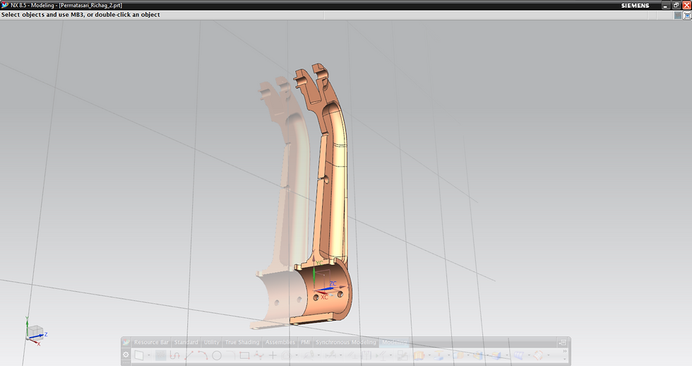
Lever section.
References:
A very insightful article! Looking forward to see more of what you have learned!